
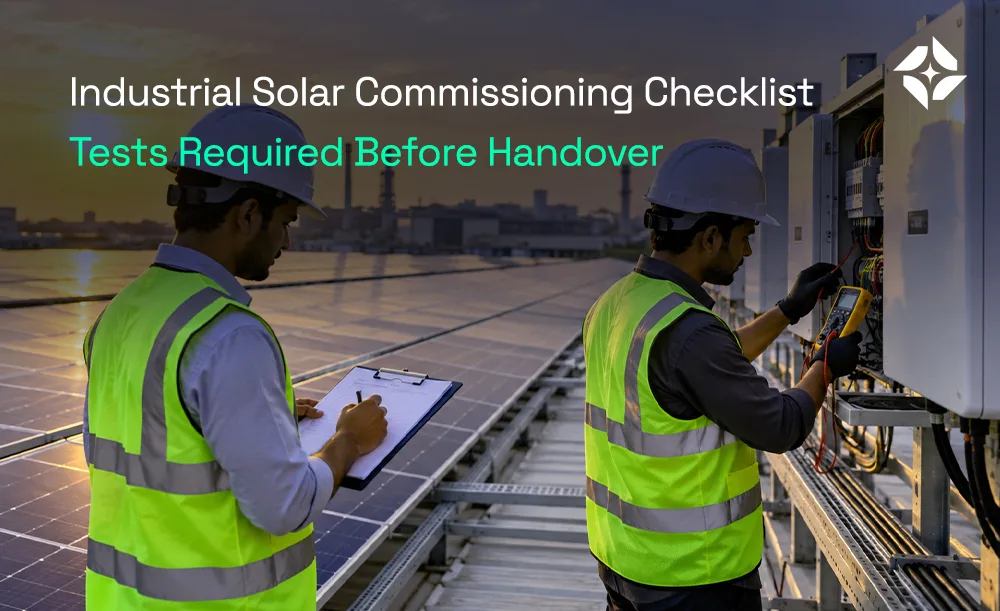
A solar plant may be fully installed, yet it is not ready for handover until the required checks and tests are complete. For an industrial site, a missed cable fault, weak earth connection or incorrect inverter setting can cause delays, safety risks and lost output. An industrial solar commissioning checklist helps the project team confirm that key parts have been inspected, tested and recorded before the plant enters service. At Raynex Power Solution, we recommend treating commissioning records, safety checks and customer handover as parts of the same process.
This guide covers the main visual inspections, DC and AC tests, inverter checks, grid protection tests and documents to review before handover. It also includes a sample test record that project teams can adapt to their own site. The exact test scope must follow the approved project documents, applicable Indian rules, relevant standards and equipment instructions. Only trained and authorised staff should carry out electrical tests and energisation work.
What Is Industrial Solar Commissioning?
Industrial solar commissioning is the process of checking and testing a solar PV plant after installation and before it is accepted for normal use. It helps confirm that the modules, cables, inverters, protection devices, earthing and monitoring equipment have been installed and work as required. The team records the test results and checks them against the approved project criteria. Any faults must be assessed and closed before the relevant part of the plant is accepted.
Commissioning is not the same as installation or grid synchronisation. Installation covers the physical work, while commissioning checks the completed work and its function. Grid synchronisation is a separate step that allows the plant to operate in line with the utility supply and approved settings. The required checks depend on the plant size, system type, connection arrangement and project scope.
The international standard IEC 62446-1 covers inspection, commissioning tests and customer documentation for grid-connected solar PV systems. The US Department of Energy also points commercial and industrial system owners to IEC 62446 for system records, array tests and whole-system performance checks. The project team should confirm the applicable edition and local requirements before preparing its test plan.
Pre-Commissioning Safety and Document Checks
Before testing begins, the team should confirm that the site is safe to inspect and that the right project records are available. Electrical work should follow the approved isolation plan, site safety rules and safe work procedures. The team should identify all sources that may energise the circuit, including the grid, inverters and any other connected equipment. Only authorised staff should remove covers, test live circuits or operate switching equipment.
The documents should match the plant that has been installed. If the drawings show a different string layout, cable route or inverter setting from the actual site, the team should resolve the difference before final acceptance. Test instruments should be suitable for the task and have valid calibration records where required. The team should also record who performed each test, when it was done and which instrument was used.
Pre-Commissioning Checklist
- Approved single-line diagram and latest drawings are available.
- Module layout and string schedule match the installed plant.
- Equipment labels, ratings and serial numbers have been checked.
- Cable routes and isolation points are marked.
- Required permits, risk checks and isolation steps are in place.
- Test instruments are suitable for the planned checks.
- Inverter manuals and manufacturer instructions are available.
- Structural, mechanical and electrical inspection records are ready.
- Any open installation defects have been listed for review.
Industrial Solar Commissioning Checklist: Visual Inspection
A visual inspection can find many issues before electrical tests begin. The team should check the modules, mounting frames, cables, connectors, junction boxes, inverters and electrical panels against the approved drawings. Look for damaged parts, loose fittings, poor cable support, water entry, missing labels and signs of heat or corrosion. Record each issue with a location, photo and action owner so it can be tracked to closure.
Solar Modules and Mounting Structures
Check the modules for cracked glass, damaged frames, loose clamps and other visible defects. Confirm that the module type and arrangement match the approved layout. Inspect the mounting frames, fasteners, supports and roof attachment points for damage or signs of movement. Any required torque checks should follow the manufacturer’s instructions and the project specification, rather than a guessed value.
DC Cables, Connectors and Combiner Boxes
Check that DC cables are supported, protected from sharp edges and routed away from areas that could damage the insulation. Connectors should be compatible, correctly fitted and free from visible damage. The team should inspect combiner boxes, glands and cable entries for secure fitting, correct labels and suitable environmental protection. Cables should not rest in standing water or hang where they may be pulled or crushed.
Inverters, AC Panels and Isolation Points
Confirm that inverter models and ratings match the approved equipment list. Inspect the AC panels, isolators, circuit breakers and protective devices for correct labels and access. Check that cable terminations and panel covers have been completed as required by the approved drawings and manufacturer instructions. Any damage, missing covers or unclear labels should be resolved before the relevant equipment is put into service.
Earthing, Bonding and Surge Protection
Inspect the protective earth conductors and bonding links that connect module frames, metal structures, inverter enclosures and other exposed conductive parts. Confirm that connections are secure and follow the approved earthing layout. Check the installed surge protection devices and lightning protection arrangements against the project documents. The inspection should confirm that required components are present, correctly connected and accessible for future checks.
DC Electrical Tests Before Handover
DC tests help confirm that the module strings and DC circuits have been connected correctly and are in a suitable state for operation. The test plan should state which circuits need testing and how the results will be recorded. The team should compare readings across similar strings and investigate unexplained differences. Test methods and acceptance limits must follow the applicable standard, approved design and equipment instructions.
String Polarity Test
A polarity test confirms that the positive and negative conductors are connected as intended. Incorrect polarity can damage equipment or prevent a circuit from operating correctly. The test should be completed with a suitable meter and the approved safe work method. Record the result for each string or circuit in the test schedule.
Open-Circuit Voltage and String Current Tests
Open-circuit voltage, often called Voc, is measured with the string disconnected from its normal load under the approved test method. The result should be compared with the expected value for the module count and the test conditions. String current checks can help identify wiring issues or differences between strings, but the correct method depends on the circuit and test plan. Readings should be assessed with due regard to sunlight, module temperature and other conditions at the time of testing.
A string that gives a different result from similar strings may have a wiring fault, a damaged module, shade or another issue. The team should investigate the cause instead of accepting the result based on a single reading. Record the measured value, test conditions and any follow-up action. Do not compare readings taken under very different sunlight conditions without accounting for those differences.
DC Insulation Resistance Test
An insulation resistance test checks the condition of insulation between the relevant conductors and earth, using the approved method for the system. The correct test voltage and acceptance limit depend on the circuit, equipment and applicable standard. Sensitive devices, including inverters and surge protection parts, may need to be isolated as directed by the manufacturer before testing. Incorrect test settings or connections can damage equipment or create a safety risk.
The team should record the circuit tested, test voltage, measured resistance, instrument details and acceptance basis. If a result is below the required limit, the circuit should be investigated and corrected before it is accepted. Moisture, damaged insulation, poor cable entries or faulty connectors may be possible causes. Retest the affected circuit after corrective work and keep both the original and final results.
Protective Earth Continuity
Earth continuity testing checks that the required protective connections form a reliable path. The test should cover the relevant metal frames, equipment enclosures and bonding points identified in the approved earthing plan. The test method and acceptance criteria should follow the project requirements and applicable electrical rules. Any failed connection must be repaired and retested before the related equipment is accepted.
When to Use I-V Curve Testing and Infrared Inspection
I-V curve testing measures the relationship between current and voltage from a module or string under known test conditions. It can help assess output issues where the basic commissioning tests do not explain a difference between strings. Infrared inspection can help identify hot spots, poor connections and other temperature-related faults. These tests may be required by the project specification or used when a fault, unusual reading or performance issue calls for further investigation.
AC, Inverter and Grid Protection Tests
The AC side connects the inverter output to the factory electrical system or the approved grid connection point. Checks should cover cable condition, termination, earthing, isolation, protective devices and phase connections. The team should confirm that the inverter settings match the approved project requirements and utility conditions. Work on AC panels and grid-connected equipment must be carried out by authorised staff under the required safety controls.
AC Cable and Insulation Checks
Inspect the AC cable routes, supports, glands, labels and terminations. Confirm that the cable size, type and protective devices match the approved design. Any insulation tests must follow the correct method for the circuit and take account of connected equipment that may need isolation. Record the results and confirm that the circuit meets its specified acceptance criteria.
Inverter Setup and Functional Tests
Check that each inverter has the correct model settings, grid parameters, date and time, monitoring connection and required firmware or configuration. Confirm that alarms are clear or properly documented and that the equipment responds as expected during the approved functional checks. Review the manufacturer’s start-up procedure before energisation. Record the inverter serial number and final settings so the site team has a reference for future service.
Protection Relay and Anti-Islanding Tests
Grid-connected plants need protection that responds to conditions such as abnormal voltage or frequency, as specified by the approved design and applicable rules. Anti-islanding protection is intended to stop the inverter from continuing to feed an isolated grid section when the utility supply is lost. The relevant tests should be performed by qualified personnel using the approved procedure and test equipment. The team should record the settings, method, results and any required utility witness or approval.
Metering, Grid Synchronisation and Export Settings
Before synchronisation, the team should confirm that the required utility approvals, metering arrangements and protection checks are complete. The inverter should connect only under the approved conditions and settings. Check the meter readings, monitoring data and export controls where they apply to the project. The final record should show the date of synchronisation, relevant approvals and any conditions that remain open.
Solar Plant Performance Verification
Performance verification helps confirm that the plant operates as expected under the conditions present during testing. A single output reading does not prove the annual energy yield because sunlight, module temperature, shade and system losses change throughout the day and year. The test record should note the weather, irradiance where measured, module temperature, inverter output and other relevant readings. These details help the team assess the result in context.
Initial Generation and Monitoring Checks
Once the required safety and electrical checks have passed, the team can verify that the monitoring platform receives data from the inverters and meters. Confirm that plant capacity, device names, timestamps and key readings appear correctly. Check that alerts and communication links work as specified. The handover record should include the monitoring login process and the person responsible for managing access.
Performance Ratio and Expected Output
Performance ratio is one measure used to assess a solar plant’s output against the solar energy available to it, after accounting for system capacity and other defined factors. Its calculation requires suitable data and a clear method, so the team should not infer a reliable value from a brief visual check. If a performance test is part of the contract, follow the agreed method and measurement period. Record any limits caused by weather or missing data.
The owner should receive a clear note on the difference between commissioning results and long-term energy estimates. A short test can show that equipment starts and responds correctly, but it cannot confirm a full year’s generation. Longer-term monitoring helps show how the plant performs across changing conditions. Any forecast should state its assumptions and should not be presented as a guaranteed result.
Solar Commissioning Test Report Template
A useful commissioning report records the test, the result, the acceptance basis and the person who completed the check. This makes it easier to review faults, compare readings and confirm that corrective work is complete. The template below is a starting point and should be adapted to the approved test plan. The final record must reflect the actual equipment and site.
| Test or inspection | What to record | Acceptance basis |
|---|---|---|
| Visual inspection | Defects, photos and corrective actions | Approved drawings and inspection criteria |
| String polarity | Polarity result for each string | Approved string schedule and test procedure |
| Open-circuit voltage | Measured voltage and test conditions | Expected values and applicable limits |
| String current | Measured current and sunlight conditions | Approved test method and expected comparison |
| DC insulation resistance | Test voltage and resistance reading | Applicable standard and equipment instructions |
| Earth continuity | Test points and measured results | Approved earthing design and test criteria |
| AC circuit checks | Cable, termination and insulation results | Approved electrical design and test method |
| Inverter checks | Settings, alarms and functional results | Manufacturer instructions and approved settings |
| Grid protection | Test results and protection settings | Utility requirements and project documents |
| Monitoring and meter checks | Readings, timestamps and communication status | Project specification and utility arrangement |
Each record should also include the date, equipment or circuit reference, test instrument, instrument ID where needed, tester’s name, reviewer, result status and notes. Use clear status labels such as pass, fail or not applicable. If a test fails, record the issue, corrective action, retest result and closure approval. Do not mark a test as passed just because the plant starts running.
Documents Required for Industrial Solar Handover
The handover file should give the factory team enough information to operate, inspect and maintain the plant safely. IEC 62446-1 sets out documentation and inspection expectations for grid-connected PV systems, including records supplied to the customer. The exact package should match the project contract, local requirements and the equipment installed. Keep the final files organised and provide them in a format the site team can access later.
Handover Document Checklist
- Final as-built drawings and single-line diagram.
- Final module layout and string schedule.
- Equipment list with model numbers and serial numbers.
- Signed visual inspection and commissioning test reports.
- Inverter settings and protection configuration records.
- Applicable utility approvals and metering documents.
- Equipment warranties and supplier contact details.
- Operating manuals and maintenance instructions.
- Monitoring access details and alarm response process.
- Cleaning, inspection and preventive maintenance plan.
- Training record for the factory’s responsible staff.
- List of open defects, if any, with agreed actions and due dates.
Final Acceptance and Open Defects
Before the owner signs the handover form, the team should review the test records and check that required approvals are complete. Any open item should be clearly listed with its risk, owner, due date and required closure evidence. Safety-critical faults or failed mandatory tests must be resolved before the affected equipment is put into service. The contract and applicable rules should define how any other outstanding work is handled before final acceptance.
Common Commissioning Failures and How to Address Them
A commissioning failure should lead to a clear investigation, not a guess. The team should record the fault, isolate the affected circuit when needed and follow an approved procedure to find the cause. Corrective work should be completed by qualified staff, followed by the relevant retest. Keep the original failed result as part of the project record so the history remains clear.
| Common issue | Possible cause | Recommended response |
|---|---|---|
| Incorrect string polarity | Reversed conductors or wiring error | Isolate and correct the wiring, then retest |
| Unexpected string voltage | Wrong string count, wiring fault or test-condition difference | Check the layout, connections and expected values |
| Low insulation resistance | Damaged cable, moisture or faulty connection | Locate the cause, repair and repeat the test |
| Poor earth continuity | Loose or missing bond | Repair the connection and retest |
| Inverter alarm | Incorrect settings, wiring fault or equipment issue | Follow the manufacturer fault procedure |
| Grid protection test failure | Wrong setting, wiring issue or failed protection device | Check the approved settings and retest using the required method |
| Missing handover records | Incomplete documentation process | Assign an owner and close the record before acceptance |
Plan Industrial Solar Testing and Handover With Raynex Power Solution Pvt. Ltd
A complete industrial solar commissioning checklist helps the project team confirm that installation work has been checked, required tests have been recorded and the handover file is ready. The goal is to give the factory owner clear evidence of the plant’s condition, settings and maintenance needs. Each result should link to an approved criterion, and any failed test should have a documented path to closure. This gives the operations team a sound basis for future checks and fault review.
Raynex Power Solution provides industrial, commercial, ground-mount and residential solar services in Gujarat. For an industrial project, the commissioning plan should be agreed early and matched to the approved engineering documents, equipment manuals and site requirements. Contact Raynex to discuss your project scope and the records needed before handover.
Frequently Asked Questions
What tests are required before solar plant handover?
The required tests depend on the system type, project scope and applicable standards. Common checks include visual inspection, string polarity, open-circuit voltage, insulation resistance, earth continuity, AC circuit checks, inverter function, grid protection and monitoring. The final list should follow the approved test plan and the relevant equipment instructions. Record the results and close required faults before handover.
Who should sign the commissioning report?
The report should be completed and reviewed by the qualified people assigned under the project contract and applicable rules. The EPC team, commissioning engineer, client representative or utility may have different duties based on the project. The handover process should state who performs each test and who accepts the result. Never treat a signature as a substitute for a completed test.
Is IEC 62446-1 relevant to industrial solar?
IEC 62446-1 covers documentation, inspection and commissioning tests for grid-connected solar PV systems. It is a key reference for setting up a commissioning plan and preparing customer handover records. The project team must still confirm which edition, local standards and utility rules apply to the site. Battery-based or hybrid systems may need other standards and tests as well.
Can a plant be handed over with open defects?
It depends on the type of defect, the contract and the applicable safety and approval requirements. A failed mandatory test or an unresolved safety issue must not be ignored to meet a handover date. Other minor items may be managed through a documented action list only where the contract and project rules allow it. The owner should receive a clear record of every open item and its closure plan.